
Honeycomb jacket design principles:
Each honeycomb point is composed of a square or an equilateral triangle arrangement. Since the interval of the honeycomb jacket is smaller than that of the ordinary jacket, the flow cross-section area is smaller in the same state of Liu Liang, and the flow rate of the fluid in the chamber is significantly increased (in comparison with the general The overall jacket is 3 to 10 times higher, and the fluid forms a localized small vortex after multiple collisions with the honeycomb point. At this time, a large number of honeycombs play a role in disturbing fluid flow in the jacket, and the fluid flows through the honeycomb. It creates spoilage phenomena, constantly changing the direction of flow and velocity of the fluid, creating turbulence, destroying or thinning the original laminar layer, accelerating the exchange of heat and cooling, and thus greatly increasing its heat transfer effect. For traditional jackets In the form of reactor or heat exchanger structure, the strength of the container is not calculated according to the calculation method of the pressure vessel to calculate the wall thickness of the container due to the structural form of the honeycomb heat exchange, which reduces the wall thickness of the outer jacket and the inner cylinder. Wall thickness improves heat exchange efficiency.
Second, the structure of the honeycomb jacket:
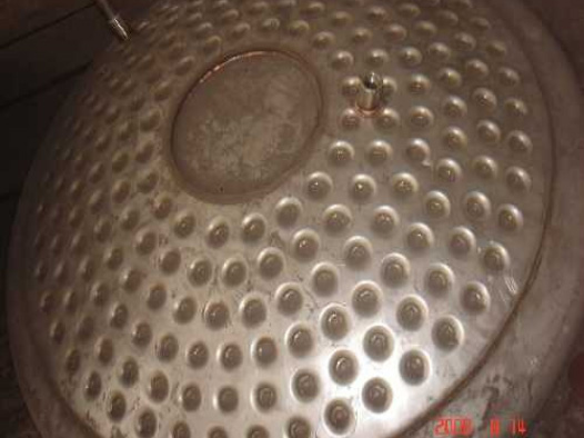
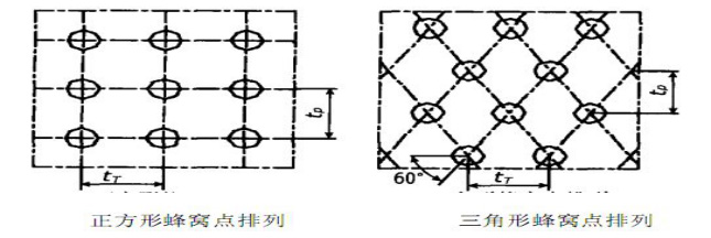
The bottom of all the honeycombs in the honeycomb jacket structure is punched with a round hole. The jacket and the shell are welded around the round hole to form a honeycomb structure, so that the honeycomb jacket is connected with the inner cylinder as a whole, since the honeycomb jacket is welded On the inner cylinder, the interior of the jacket is divided into a small rectangular container bounded by four welding points. The effect of the pressure of the fluid in the jacket on the jacket and the inner cylinder can be regarded as the support of the uniform load. The plate (see picture 01), the side length of the plate is equal to the spacing of the solder joints. This way greatly improves the force of the jacket. The interval between the honeycomb jacket and the inner cylinder is generally about 10mm, and the honeycomb arrangement There are two types of squares and triangles, the spacing between the honeycomb is generally 50mm, 65mm, etc. (see picture)
Third, equipment composition and use:
This equipment is composed of kettle body, kettle lid, honeycomb jacket, stirrer, transmission, shaft sealing device, support, etc. The kettle body and parts that are in contact with the material in the kettle are made of 304, 321, 316L stainless acid-resistant steel plate. Made to meet GMP standards. The design, manufacture, and acceptance are in accordance with the technical conditions and requirements of GB150-2011 "Steel Pressure Vessels".
Stirring form can be selected as frame type, anchor type, paddle type, etc. as required; the use of sanitary mechanical seals or ordinary mechanical seals for sealing can ensure the pressure in the tank and prevent the leakage of material inside the tank and cause unnecessary pollution.
Widely used in petroleum, chemical, rubber, pesticides, dyes, medicine, food, used to complete the vulcanization, nitration, hydrogenation, hydrocarbonization, polymerization, condensation and other processes.
Four, honeycomb jacket reactor features:
1. Due to the unique form of honeycomb, when the fluid passes through the honeycomb, sufficient turbulence and turbulence are formed to speed up the exchange of heat exchange, which is 2-3 times higher than the traditional jacket heat exchange efficiency.
2. The wall thickness of the inner barrel of the honeycomb jacket container is 30-40% thicker than the traditional jacket wall, which can greatly save the cost of equipment raw materials.
3. Honeycombs are manufactured with professional design software and special abrasive tools to ensure the stable and safe use of the equipment.
Fifth, technical parameters table:
Specifications | Actual capacity(L) | Simplified diameter(mm) | Cellular heat transfer area(M2) | Motor Power(kw) |
500L | 550 | 900 | 2.438 | 2.2 |
1000L | 1100 | 1100 | 2.867 | 4 |
1500L | 1650 | 1200 | 3.537 | 4 |
2000L | 2200 | 1300 | 4.165 | 5.5 |
3000L | 3300 | 1500 | 5.569 | 7.5 |
6000L | 6600 | 1800 | 10.323 | 15 |
10000L | 11000 | 2200 | 50.345 | 22 |
20000L | 22000 | 2400 | 101.679 | 55 |